
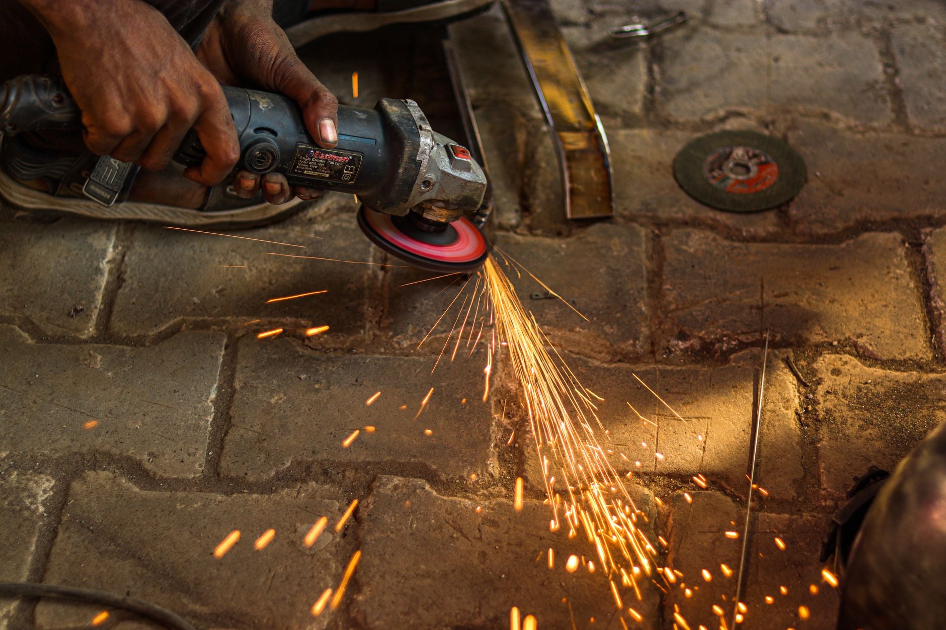
Respuesta rápida
Primero corta la energía: desconecta la esmeriladora o retira la batería, con el mismo hábito de bloqueo que se aplica a cualquier cambio de disco (KB: Prueba de sonido del disco y seguridad de montaje). Después sujeta el husillo, asienta a escuadra la llave de pernos en la tuerca de la brida y aflójala con un solo tirón firme contra el sentido de giro del disco. Una tuerca instalada con los dedos puede quedar tan apretada que cueste retirarla con la llave: ANSI B7.1 §6.10 exige que los discos con cubo roscado se aprieten en su sentido de giro (KB: Normas de rosca del husillo y del eje), y un pellizco o paro empuja la sujeción con más fuerza contra su asiento de la misma manera. Evita que vuelva a ocurrir con disciplina de torque: nunca rebases el límite ANSI B7.1 de 20 ft-lb (≈27 N·m), solo lo necesario para impedir que el disco se deslice; además, usa bridas limpias y planas y un secante de papel nuevo en los discos cuya construcción lo requiera (KB: Secante de brida y torque de montaje).
Por qué se agarrota la tuerca: torque, no mala suerte
1. Se instaló demasiado apretada. La regla de montaje ANSI B7.1 tiene una función: aprieta la tuerca solo lo suficiente para impulsar el disco e impedir que se deslice, con un límite de 20 ft-lb (≈27 N·m), salvo que el fabricante de la máquina autorice más; las bridas de varios tornillos se aprietan uniformemente en cruz hasta un máximo común de 15–20 ft-lb (ANSI B7.1 §6.8; KB: Secante de brida y torque de montaje). Si fuerzas más allá de ese valor, deformarás la brida, someterás un disco frágil a esfuerzos previos que pueden agrietarlo y tendrás garantizada una batalla en el siguiente cambio. En una sola acción, el torque excesivo causa el agarrotamiento y crea un riesgo de estallido.
2. Se apretó sola. Las roscas de las esmeriladoras están orientadas para que el accesorio se apriete en su sentido de giro, un requisito de diseño para los discos con cubo roscado según ANSI B7.1 §6.10 (KB: Normas de rosca del husillo y del eje). Por eso, cuando un disco de corte queda pellizcado en el corte o el disco se atora y se detiene, el impulso del husillo empuja la tuerca o el cubo con más fuerza contra su asiento. Muchas esmeriladoras modernas tienen electrónica antiatasco que detecta el bloqueo y corta el motor (KB: Control de velocidad variable y arranque suave), pero para entonces el apriete por trinquete ya ocurrió. Una tuerca que solo se agarrota después de cortes problemáticos indica un problema de técnica, no de herrajes.
3. La interfaz estaba comprometida. El husillo norteamericano de 5/8"-11 y el métrico M14 × 2 tienen dimensiones parecidas — 15.875 mm frente a 14.0 mm, con pasos distintos —, pero no son intercambiables; forzar uno sobre el otro cruza la rosca y arruina el husillo (KB: Normas de rosca del husillo y del eje). ANSI B7.1 §6.3 también exige que el disco se deslice libremente sobre el husillo; se prohíbe forzar un barreno apretado (KB: Prueba de sonido del disco y seguridad de montaje). Las bridas sucias, desgastadas o deformadas terminan el trabajo: ambas deben tener el mismo diámetro y la misma superficie de apoyo, y estar planas y limpias (OSHA 1910.215(c)(4)(i); KB: Secante de brida y torque de montaje).
Guía para diagnosticar un disco atascado
| Lo que tienes enfrente | Lo que realmente ocurrió | Cómo liberarlo | Cómo evitar que vuelva a ocurrir |
|---|---|---|---|
| Tuerca de la brida agarrotada después del uso normal | Apriete excesivo durante el montaje | Energía cortada, husillo sujeto, llave de pernos y un solo tirón firme contra el sentido de giro | Respeta el límite ANSI B7.1 de 20 ft-lb; ajusta, pero no fuerces |
| Tuerca o cubo agarrotado después de un pellizco, paro o contragolpe | El paro apretó más la sujeción en el sentido de giro | Primero libera el disco de la pieza de trabajo y luego afloja la tuerca; inspecciona el disco antes de reutilizarlo | Apoya el recorte, sujeta ambos extremos y coloca una cuña en el corte (KB: Técnica de corte) |
| El disco de láminas (disco flap) con cubo roscado no se desenrosca | Por diseño, la rosca del cubo se aprieta en el sentido de giro (ANSI B7.1 §6.10) | Con el husillo sujeto, agarra con guantes el cuerpo del disco y gira contra el sentido de rotación | Enrosca solo hasta apretar a mano; mantén las roscas del husillo limpias y sin daños |
| Disco atascado a medio corte en la ranura | La ranura se cerró sobre el disco: esfuerzo residual o recorte sin apoyo | Suelta el gatillo, corta la energía, abre la ranura con una cuña y retira el disco perfectamente recto | Corta desde el extremo apoyado hacia el extremo libre; deja que el recorte caiga hacia afuera |
| El disco no se desprende del husillo | Ajuste del barreno forzado o incorrecto, o incompatibilidad M14 / 5/8-11 con rosca cruzada | No lo golpees; cuando la tuerca esté libre, retíralo uniformemente a mano | El disco debe deslizarse libremente (ANSI B7.1 §6.3); nunca fuerces el ajuste ni mezcles roscas |
Cómo liberarlo sin arruinar el husillo
1. Corta la energía, siempre
Desconecta el cable o retira la batería antes de acercar las manos al disco; el bloqueo antes de cambiar un disco es una práctica estándar (KB: Prueba de sonido del disco y seguridad de montaje).
2. Usa la llave de pernos, no pinzas
La llave de dos pernos se acopla a escuadra con la tuerca; las pinzas y los desarmadores atorados en un solo orificio redondean la tuerca y dañan la cara de la brida. Una brida que ya no está plana y rectificada debe reemplazarse, porque las bridas desgastadas o deformadas concentran la carga de sujeción sobre el disco (KB: Secante de brida y torque de montaje). Sujeta el husillo con el retén propio de la herramienta y aplica un solo tirón controlado, no varios tirones bruscos.
3. Nunca golpees el disco ni hagas palanca contra él
Un disco abrasivo aglomerado es un disco cerámico frágil y sensible a los esfuerzos; las cargas puntuales inician microgrietas que terminan en un estallido a la velocidad de operación (KB: Secante de brida y torque de montaje). La palanca se aplica a la llave y la tuerca, nunca a través del abrasivo. Los discos de corte delgados casi no tienen resistencia lateral; la torsión y la carga lateral son las causas principales de rotura a medio corte (análisis de roturas; KB: Técnica de corte).
4. Si el disco está atascado en la pieza, libera primero el corte
Un atasco a medio corte suele ocurrir porque la ranura se cierra de golpe: los esfuerzos residuales del material laminado o soldado actúan como un resorte comprimido y, cuando se liberan, cierran la ranura sobre el disco (KB: Técnica de corte). Suelta el gatillo, corta la energía, introduce una cuña en la ranura para volver a abrirla y saca el disco perfectamente recto, sin torcerlo ni mecerlo. Los discos de corte que sobreviven son los que se retiran alineados con el corte.
5. Inspecciona antes de volver a confiar en el disco
El pellizco, la torsión y el atasco son las causas principales de que los discos estallen durante el servicio, y el daño no siempre es visible. Los discos con aglomerante de resina no pueden someterse a la prueba de sonido (ring test), porque el aglomerante orgánico amortigua el sonido; por eso, inspecciónalos visualmente y deséchalos ante cualquier despostilladura, grieta o bamboleo (KB: Prueba de sonido del disco y seguridad de montaje). Después de volver a montarlo, haz funcionar el disco detrás de la guarda durante aproximadamente un minuto, con todas las personas alejadas del plano de rotación. Nuestra guía sobre seguridad de discos de desbaste y RPM máximas incluye toda la rutina previa al uso.
El hábito correcto con la arandela de papel
La « arandela de papel » entre la brida y el disco se llama correctamente secante y, cuando se necesita, no es opcional: OSHA 1910.215(c)(6)(i) exige secantes entre las bridas y las superficies del disco para distribuir uniformemente la presión de sujeción; de lo contrario, la brida rígida se apoya en los puntos altos y genera cargas puntuales que pueden agrietar el aglomerante por esfuerzo (KB: Secante de brida y torque de montaje). El hábito es sencillo: un secante nuevo por lado en cada montaje, nunca reutilizado, porque un secante comprimido de nuevo ya no se deforma uniformemente (CCOHS; KB: Prueba de sonido del disco y seguridad de montaje).
Igual de importante es saber dónde el secante no corresponde. OSHA 1910.215(c)(6)(ii) exenta las construcciones que ya distribuyen la carga: los discos de desbaste (centro deprimido) Type 27 y Type 28, los discos de corte reforzados y las puntas montadas se instalan sin papel (KB: Guarda del disco y secante). Esto abarca la mayoría de los accesorios que funcionan en una esmeriladora angular: los discos de desbaste (centro deprimido) y los discos de corte de un taller de fabricación están diseñados para usarse sin secante. Regla de campo: las bridas de metal desnudo que sujetan un disco aglomerado sencillo necesitan secantes en ambos lados; un disco con su propio respaldo de acero o moldeado no los necesita.
Los valores de montaje que mantienen útil una tuerca
| Regla | Valor | Fuente |
|---|---|---|
| Torque de la tuerca del husillo | Solo lo suficiente para evitar el deslizamiento; nunca más de 20 ft-lb (≈27 N·m) sin la aprobación del fabricante de la máquina | ANSI B7.1 (KB: Secante de brida y torque de montaje) |
| Bridas de varios tornillos | En cruz y uniformemente, hasta un máximo común de 15–20 ft-lb | ANSI B7.1 §6.8 |
| Tamaño de la brida | Ambas bridas ≥ 1/3 del diámetro del disco, del mismo diámetro y con igual superficie de apoyo | Referencia OSHA: 1910.215(c)(1), (c)(4)(i) |
| Rebaje de la brida | Bridas rectas con rebaje de ≥ 1/16 in en el lado del disco | OSHA 1910.215(c)(5)(i) |
| Secantes | Un secante nuevo por lado, nunca reutilizado; se exentan los Type 27/28 y los discos de corte reforzados | OSHA: 1910.215(c)(6); CCOHS |
| Ajuste del barreno | El disco se desliza libremente sobre el husillo; se prohíbe forzar un barreno apretado | ANSI B7.1 §6.3 |
| Roscas del husillo | 5/8"-11 UNC (Norteamérica) frente a M14 × 2 (métrico): no son intercambiables; usa el adaptador correcto o no lo montes | KB: Normas de rosca del husillo y del eje |
Cada fila elimina una razón para necesitar una barra de fuerza en el siguiente cambio de disco. El panorama general — quién redacta estas reglas y cómo se someten los discos a pruebas de estallido conforme a ellas — se encuentra en nuestro resumen de normas de seguridad para abrasivos (EN 12413, oSa, ANSI).
Evita el atasco a medio corte
Como un paro convierte una tuerca ajustada a mano en una tuerca agarrotada, evitar atascos también evita el agarrotamiento. Las reglas de técnica son las mismas que mantienen íntegros los discos delgados: sujeta ambos extremos, pero apoya el recorte para que caiga hacia afuera; corta desde el extremo apoyado hacia el extremo libre; mantén el disco perfectamente perpendicular, sin presión lateral ni torsión; reduce la presión cuando el recorte se separe en lugar de romper el último puente; y, en material deformado, sujeta con el lado convexo hacia abajo (KB: Técnica de corte). Las cuñas en la ranura de materiales estructurales o soldados forman parte de la técnica, no son señal de derrota. La elección del disco también importa; consulta cómo elegir un disco de corte y la sección de preguntas sobre RPM y espesor de discos de corte.
Los herrajes también pueden eliminar el error humano. Las tuercas de bloqueo de cambio rápido apretadas a mano se liberan sin una llave de pernos, y los montajes a presión sin herramientas ajustan mecánicamente la fuerza de sujeción, con lo que eliminan por completo el apriete excesivo o insuficiente como modos de falla (KB: Secante de brida y torque de montaje); para discos pequeños de 2"–3", los portadiscos de cambio rápido (Tipo R/TR) evitan por completo el husillo roscado. Además, los discos de láminas con cubo roscado que se enroscan a mano se recomienda apretarlos únicamente a mano.
Preguntas frecuentes
¿Por qué se sigue agarrotando la tuerca de la brida de mi esmeriladora angular?
Hay tres causas posibles: la tuerca se apretó más allá del límite ANSI B7.1 de « solo lo suficiente para evitar el deslizamiento » (con límite de 20 ft-lb); un pellizco o paro apretó más la rosca orientada en su sentido de giro; o la interfaz está comprometida: piezas M14/5/8-11 con rosca cruzada, barreno forzado o bridas sucias y deformadas (KB: Secante de brida y torque de montaje; Normas de rosca del husillo y del eje).
¿Hacia qué lado giro la tuerca de la brida para aflojarla?
Contra el sentido de giro del disco. Las roscas de las esmeriladoras están orientadas para que el accesorio se apriete en el sentido en que gira; ANSI B7.1 §6.10 exige exactamente eso para los discos con cubo roscado. Por lo tanto, se aflojan en el sentido contrario, con el husillo sujeto y la energía desconectada (KB: Normas de rosca del husillo y del eje).
¿Necesito una arandela secante de papel en un disco de esmeriladora angular?
Por lo general, no. Los discos de desbaste (centro deprimido) Type 27 y Type 28 y los discos de corte reforzados están exentos según OSHA 1910.215(c)(6)(ii), porque su construcción distribuye la carga de sujeción. Los secantes son obligatorios cuando las bridas de metal desnudo sujetan un disco abrasivo aglomerado sencillo: un secante nuevo por lado, nunca reutilizado (KB: Guarda del disco y secante).
¿Qué tanto debo apretar la tuerca de la brida de una esmeriladora angular?
Solo lo suficiente para que el disco no se deslice sobre la brida motriz bajo carga y nunca más de 20 ft-lb (≈27 N·m), salvo que el fabricante de la máquina autorice una cifra mayor (ANSI B7.1; KB: Secante de brida y torque de montaje). El apriete excesivo deforma la brida y somete el disco a esfuerzos previos que pueden agrietarlo: es un peligro de estallido, no seguridad adicional.
¿Puedo seguir usando un disco que quedó pellizcado o se detuvo durante un corte?
Solo después de una inspección rigurosa. El pellizco, la torsión y el atasco son las causas principales de que los discos estallen durante el servicio, y los discos con aglomerante de resina no pueden someterse a la prueba de sonido (ring test), porque el aglomerante orgánico amortigua el sonido. Inspecciona visualmente para detectar grietas, despostilladuras y bamboleo; deséchalo ante cualquier duda y haz funcionar el disco ya montado detrás de la guarda durante aproximadamente un minuto antes de que toque la pieza de trabajo (KB: Técnica de corte; Prueba de sonido del disco y seguridad de montaje).
¿Puedo instalar un disco M14 en un husillo 5/8-11 para evitar que se agarrote?
No. M14 (14.0 mm, paso de 2 mm) y 5/8"-11 (15.875 mm, 11 TPI) son lo bastante parecidos como para iniciar a la fuerza, pero lo bastante distintos como para arruinar la rosca; es una causa clásica de agarrotamiento y un problema de seguridad, ya que un disco con la rosca cruzada puede quedar sujeto de forma insegura. Usa un adaptador de rosca adecuado o el disco con la rosca correcta; nunca fuerces el ajuste (KB: Normas de rosca del husillo y del eje).